__
Image 01 / Stage 02
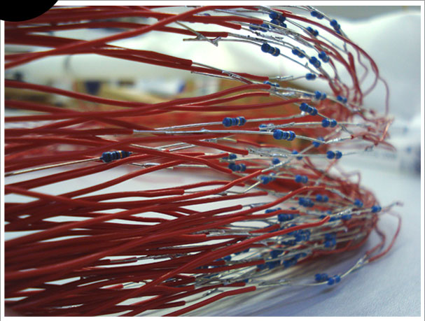
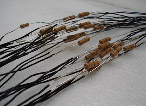
80 resistors with cables.
The project is hosted by:

The project is funded by:


The project is sponsored by:


The project is supported by:

![]()

Stage 2_Design and technology
development
September 2007 - August 2008
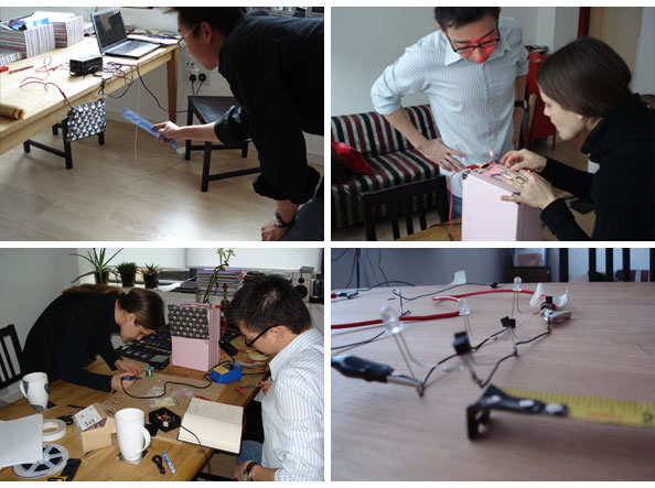
During this period the theoretical and contextual research was continued alongside with the practical experiments in order to support the conceptual refinement of the project. Zane and Jackson spent two intense research stays at TITV Greiz in Germany in order to advance the development and testing of the 'E-Static Shadows' prototypes.
__
Image 02 - 05 / Stage 02
Testing the sensitivity of the newly produced interactive textile structure sample to static charges. Verdict: we shall search for other appropriate sensors available on the market which are more sensitive to electrostatics.
__
Image 06 + 08 / Stage 02
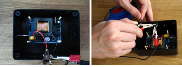
One of the biggest problems when working with electrostatics in non-laboratory environments is that it constantly changes depending on room humidity, on materials we are wearing, etc. Dr. Kevin Chai (University of Glasgow) made and kindly donated this ion generator to our project. It proved to be a very good tool to measure the sensitivity of the e-textles systems to static charges. It generates a constant amount of negative charges (voltage - 5000 V, source - 12V) and gives us at least one constant parameter against which we can measure the sensitivity of our textile structures to electrostatics.
__
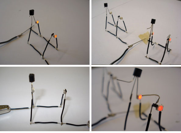
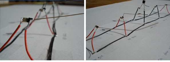
Image 09 + 14 / Stage 02
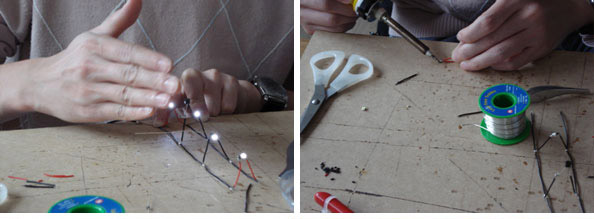
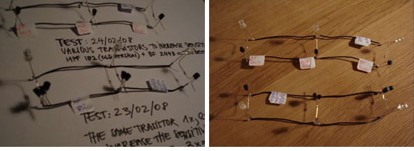
Testing various types of transistors using the ion generator.
__
Image 15 - 18 / Stage 02
Testing our newest (nr. 17) e-weave structure using the ion generator.
__
Image 19 - 22 / Stage 02
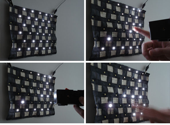
Visual and functional tests exploring the aesthetic potential of the textile structures employing a layer of various thin fabrics to change the quality of the light produced by the LEDs. Images 19 and 20 demonstrate that the fabric screen does not affect the sensitivity of the e-textile structure - it is still picking up on the negative charges in the environment.
__
Image 23 - 24 / Stage 02
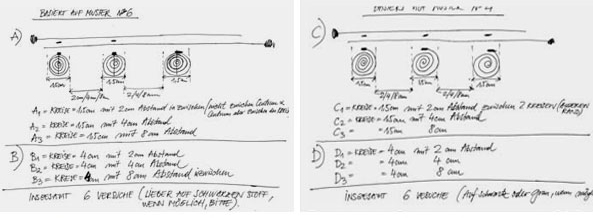
We were also curious to test if CAD stitching could be used to develop e-textile systems for our purpose. Technical sketches for stitched sensors.
__
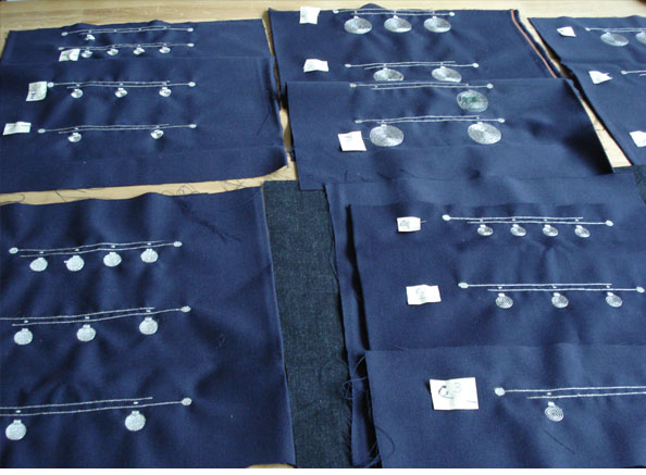
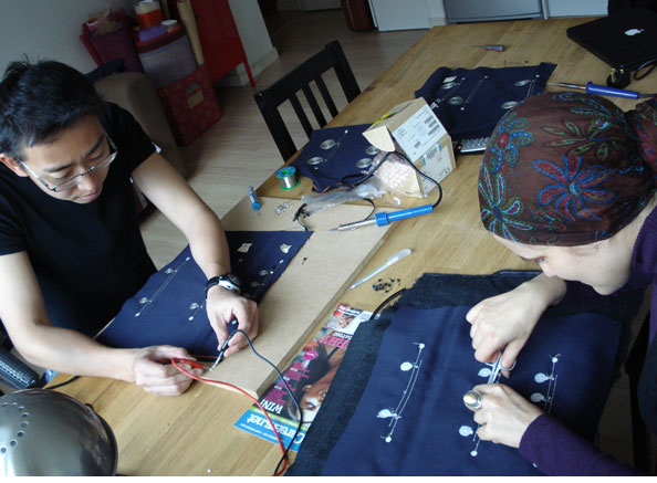
Image 25 - 26 / Stage 02
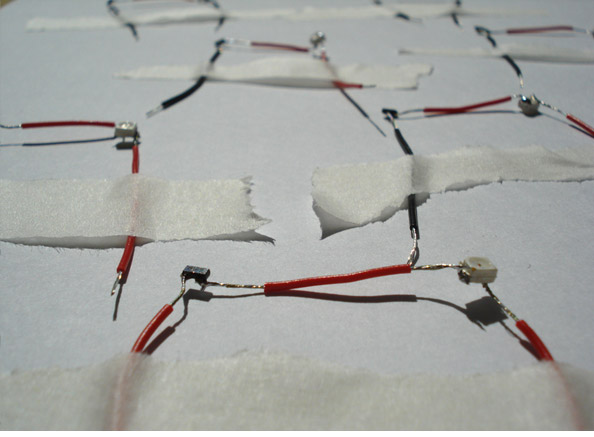
The realised stitch samples including the soldering of electronic components onto them.
__
Image 27 - 31 / Stage 02
Further ion generator tests to compare the potential of stitched and woven e-textile structures.
__
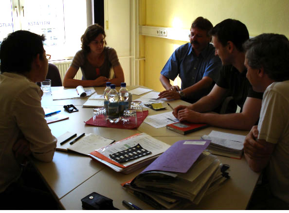
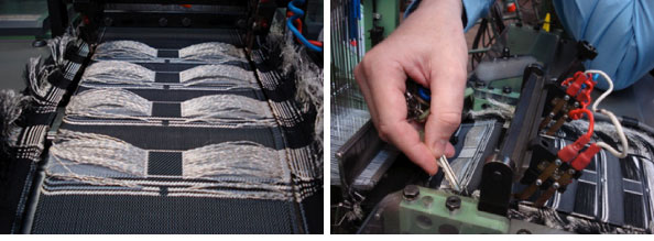
Image 32 - 35 / Stage 02
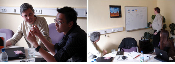
Our second working visit at TITV Greiz started with a brainstorming meeting between Dr. Neudeck, Mr. Thurner, Zane and Jackson in order to establish the most effective way to improve the e-weave structures and the integration of micro-electronics. We were concentrating on the woven structures mostly.
__
Image 36 - 40 / Stage 02
Our search for better transistors is neverending: they have to be smaller and more sensitive to static charges. Further comparative tests of the transistors outside the e-weave structure.
__
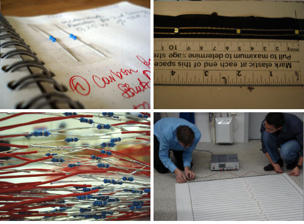
Image 41 - 48 / Stage 02
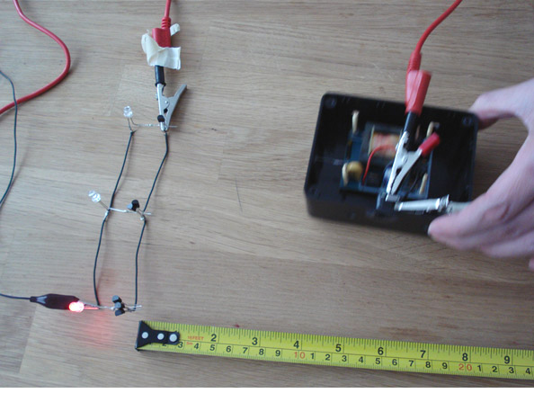
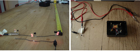
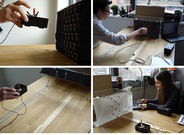
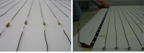
Preparation of a mock-up real size demonstrator to measure how much electrical power we need to light up all our LEDs in the planned final cloth (for 2m x 1m area, distance between LEDs = 4cm which is = 1250 LEDs ) and what type of conductive threads/wires and how many of them we need for power lines to construct such system. We find out that our intended final textile module requires 3V 3A = 9W.
__
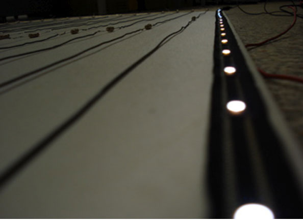
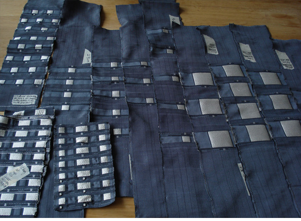
Image 49 / Stage 02
These resistors are used to simulate the woven rows full of bright 20 mA LEDs and to save time on soldering.
__
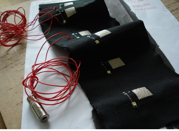
Image 50 - 53 / Stage 02
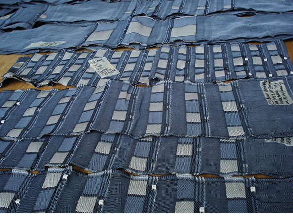
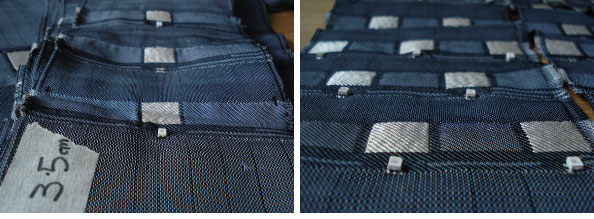
The optimised w eave structure samples. The no. 17 weave structure is used as a base structure (modified depending on the desired size of the sensors and the distance between the sensors).
__
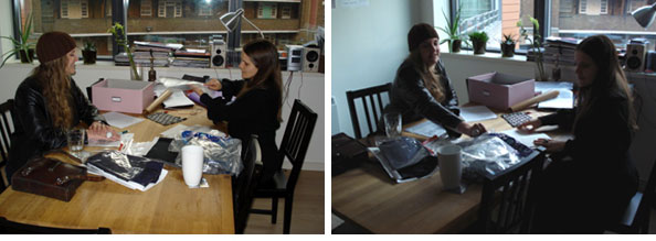
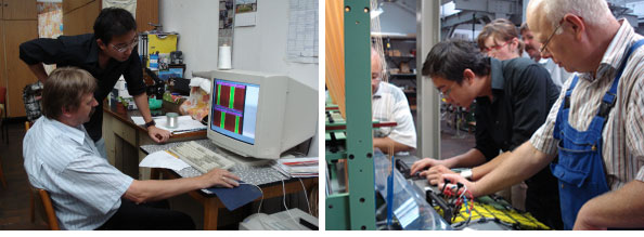
Image 54 - 55 / Stage 02
Zane is meeting our materials consultant Natalie Stingelin-Stuzmann to discuss materials which would enhance the performance of the end instalation as well as whether organic transistors with better properties could be specially developed at the Queen Mary University for the project.
__
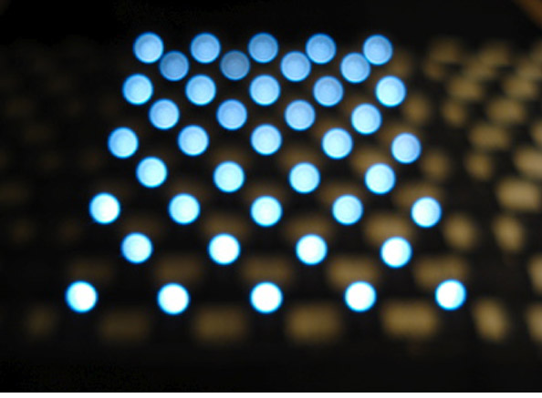
Image 56 / Stage 02
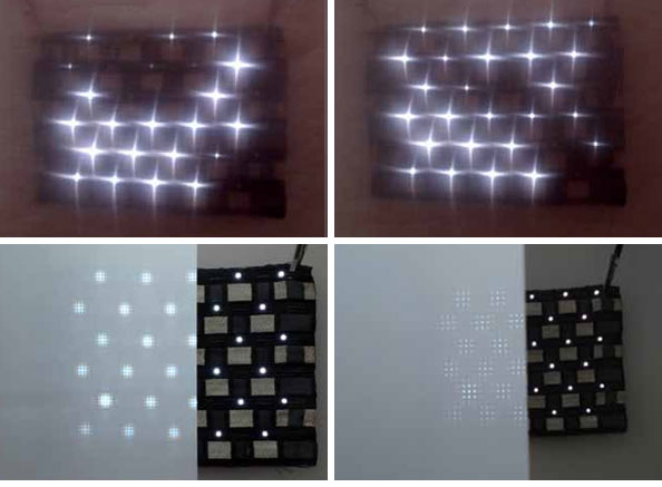
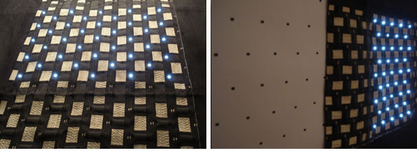
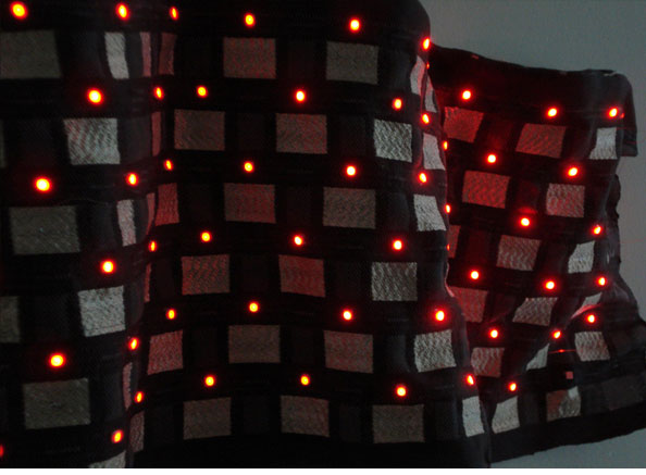
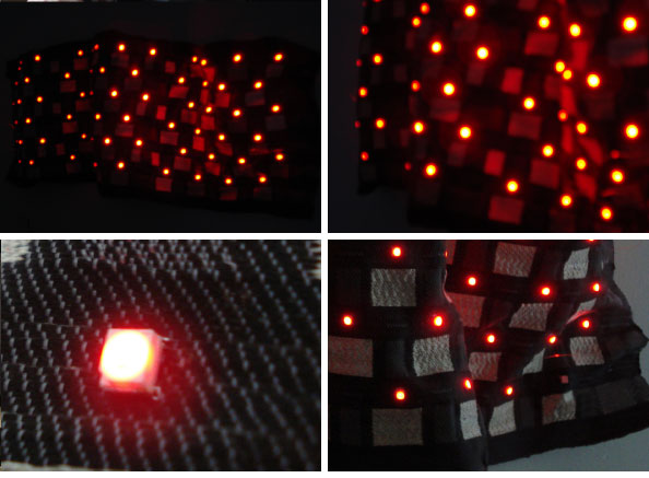
In order to plan the aesthetic performance of the e-cloth we carried out a series of visual tests which helped us to decide on the distances between the LEDs, size and format of the e-cloth in relation to the human body as well as the shape and size of the woven sensors. The e-cloth performs very differently in day light and in dark environments.
__
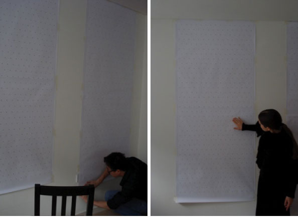
Image 57 - 62 / Stage 02
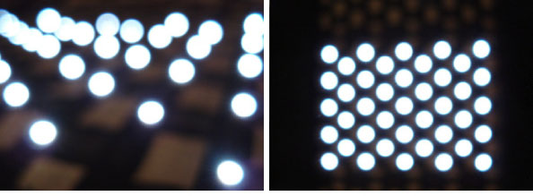
IWe considered distribution of LEDs across the fabric in 4cm, 5cm and 6cm distances. For that reason large 1 : 1 scale paper printouts were made to test the visual qualities of the three versions.
__
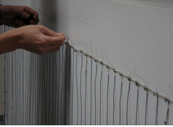
Image 63 - 64 / Stage 02
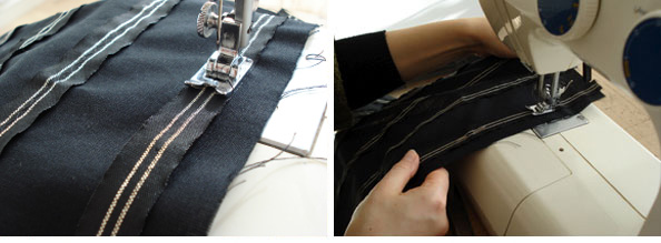
Sewing power lines for visual tests.
__
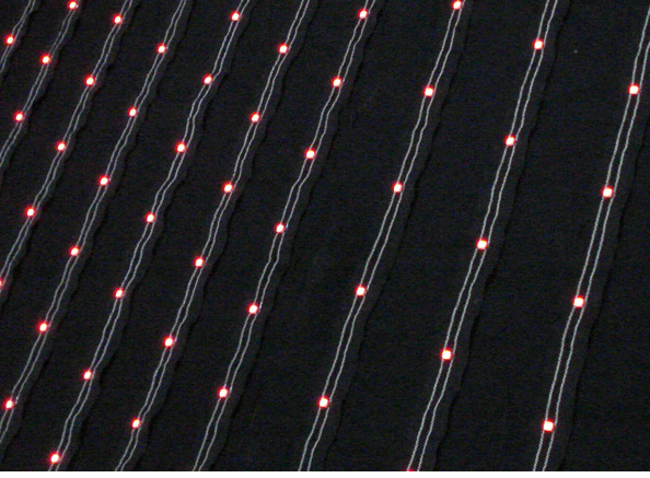
Image 65 - 69 / Stage 02
Distribution of LEDs across the cloth in 4cm, 5cm and 6cm distances. We think that the 5cm grid/repeat may work the best. It would also save us many hours of soldering when producing the final large scale prototypes without compromising on the aesthetic impact of the e-cloths. A variation in the distribution of LEDs (as seen in the lower images) would also be interesting. However, this adds to the technical variables that still need to be tested on the weave system when next we go to TITV Greiz and we are running out of time... But this could be considered in the future.
__
Image 70 - 71 / Stage 02
Preparing the first all working prototype - cutting the conductive threads and checking the electrical properties.
__
Image 72 - 76 / Stage 02
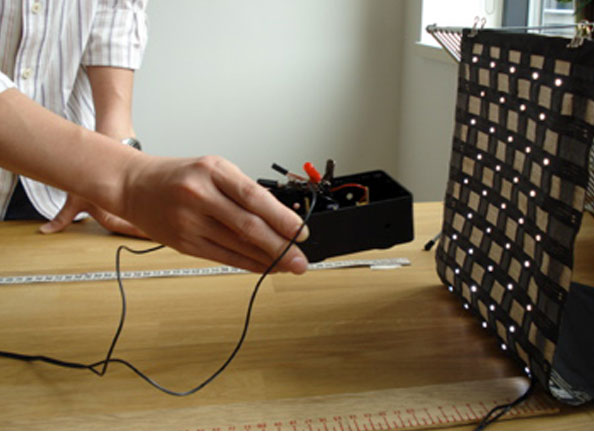
In order to determine the visual impact of the planned installation at the planned Dana Centre exhibition, further visual tests were carried out using the small size working prototype. These tests changed our initial ideas about the installation staging in the gallery space and the entire choreography of how people will move in this space interacting with the work. We would like to create a more sculptural e-textile membrane as seen in this small prototype.
__
Image 77 - 81 / Stage 02
Since May 2008 Dr. Tim Blackwell from the Goldsmiths Digital Studios has joined our team to replace Dr. Andres Melo. From now on he agreed to be responsible for the sound aspects on the project.
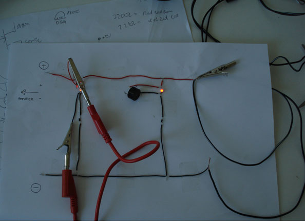
We tested some speakers and buzzers but none of them were really doing the job - the speakers did not work at all (as the ones which we could still imagine being integrated into the textile system are too small) but the buzzers produce constant sound which is not variable and which switches off in reaction to e-static charges. We are aiming for a reverse effect - sound being created in reaction to e-static charges.
__
Image 82 - 85 / Stage 02
We also tested a "small" amplifier but all these large electronic components are not appealing to us. We are looking for something small that seemlesly could be integrated into our textile system.
__
Image 86 / Stage 02
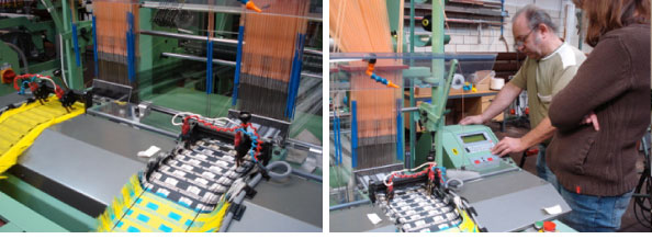
Our third working visit at TITV started with a meeting where Zane and Jackson discussed the prepared schedule for the intensive week ahead with Dr. Neudeck, Mr. Rotsch, Ms Roth, Ms Oschatz and Mr Thurner.
__
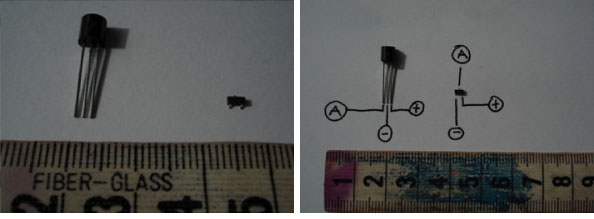
Image 87 - 90 / Stage 02
We really liked the idea of using very small transistors for our e-cloth as this meant that we can miniaturize the hard electonic parts significantly and achieve a trully flexible textile system. After we tested many commercially available small transistors for their sensitivity to static charges we found one which was acceptable. However, the change of the transistor size had a dramatic impact on the e-textile structures we were weaving/stitching so far: the design of the new transistor created new problems due to the fact that the antenna gate is placed between the "+" and "-" leaving pratically little options for woven circuits... Will we be able to develop the woven e-structure as we desire?
__
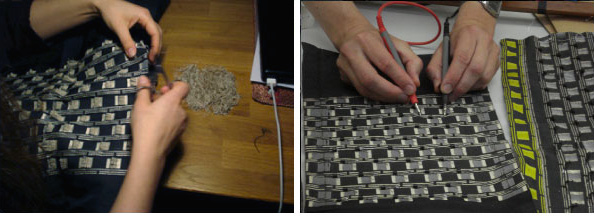
Image 91 - 94 / Stage 02
A completely new circuit for the small transistor has to be designed, woven and tested.
__
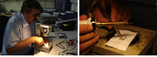
Image 95 - 96 / Stage 02
The new circuit for the small transistor is so small that Dr. Neudeck needs a microscope to check it...to cut the curcuit...and to solder the transistor and LED... It is so tiny that it is difficult to avoid shortcuts. It needs to be optimised for better cutting of the conductive threads and soldering but in priciple the new structure works.
__
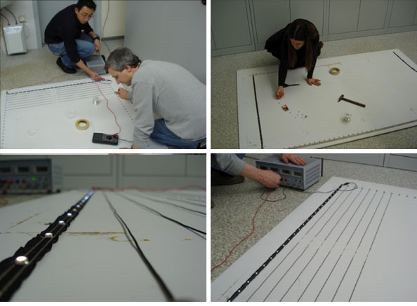
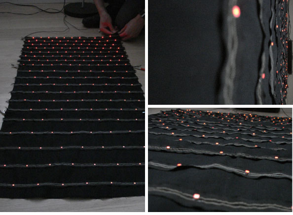
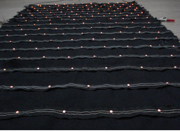
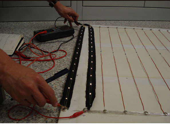
Image 97 - 111 / Stage 02
In parallel to weaving we prepared one more real size mock-up demonstrator (accocrding to our new design of 0.7m x 4m textile modules with the distance between LEDs = 5cm) to measure how much power we need to light up all our LEDs and how many conductive threads/wires we need for the power lines to support such a system. We used 80 resistors to simulate the rows equipped with 20 mA LEDs to save time on soldering.
__
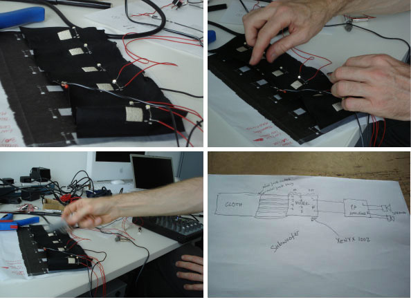
Image 112 - 116 / Stage 02
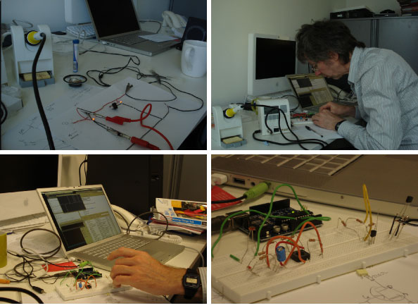
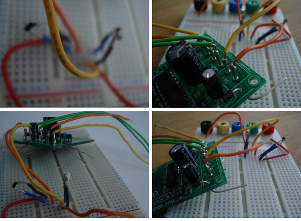
We continued our sound experiments by using an amplifier, speakers and a mixer to directly pick up the noise produced by the electric current running through the e-cloth and amplifying that sound. When static charge is introduced, the textile circuit creates low and deep hum which is varied depending on the type and conditions of input (hand, plastic, distance, speed, etc). This solution works well and gives a nice spectrum of sound but it uses amplifiers and speakers externally.
We have also worked out the sound technology requirements and the related practicalities re our final installation at the Dana Centre. Since only one LED/transistor set can be responsible for the sound production at one time, we have decided that such "sound modules" will be distributed around the e-cloth at approx. 0.5m distance from each other. The amplifiers and loudspeakers will be hidden above the installation, on ceiling panels.